Setting up UDIMs in Blender: Step-by-step

Tutorial / 04 May 2023

In a previous article, we had a look at texel density and how taking it into consideration can help us achieve a feeling of consistency and immersion in our 3D scenes. We learned that often, a render can feel strange because the objects have textures with resolution disproportionate to their size and visual importance, and that by maintaining that proportionality across the textures, we get optimised projects and better looking renders.  

There are, however, exceptions that can and in many cases should be made. We see these exceptions mainly in assets that are likely to be viewed up close and often throughout a sequence, or a point of focus in a still image. Assets like these are typically granted much more texture resolution/texel density to allow their finer details to shine through a shot, and to remain crisp regardless of their distance from the camera.  

Of course, this would mean that our “Hero” assets will need to have their UV shells or islands take more space in the UV grid, and larger Texture Map sizes, which can be a problem if the asset is relatively large and consists of a single mesh.

Source: “Ship Pinnace” by James Ray Cock, Nicolo Zubbini and Rico Cilliers, available at Poly Haven

A model like this, for example, could consist of many separate meshes. Depending on each mesh’s size in the scene, a single or group of meshes can occupy their own 0-1 UV grid (but this could mean more textures than we’re comfortable dealing with for one object).

Credits:* Monster, designed and created by Daniel Bystedt. CC BY-SA 3.0 license

For a model like this, that approach may not be as feasible. This is where UDIMs come in. In this article, we’ll go over what UDIMs are, and how we can use them on our own assets. 

‍Need some rendering power on an upcoming project? Check out our Blender Render Farm and get $50 worth of free credits upon registering! P.S. we support scenes that use UDIMs ;)

What are UDIMS  

UDIM tiling is a texture mapping technique used in 3D graphics to improve the efficiency and quality of texture mapping. UDIM stands for "U Dimension" and allows us to distribute UV islands across several textures, effectively affording the islands more space to work with than the 0-1 grid we’re used to. This can also allow for different resolutions for different parts of the mesh. The UDIM tile system assigns a unique index number to each tile, with the first being 1001 and subsequent tiles being placed to the right of the main tile or in a new row above it.

The panel above the creature model shows its UV islands distributed across 5 UDIMs, which makes each region of the model capable of having much more texel density using a single material. This also means it’s still possible to paint across the whole model when texturing.

UDIMs offer several advantages over traditional UV mapping techniques:

  1. Higher texture resolution: By dividing a texture into smaller tiles, each tile can have its own resolution. This allows for more detailed and higher resolution textures, especially for larger meshes with geometry of varying importance.
  2. Flexibility and efficiency: UDIMs provide greater flexibility and efficiency in texture creation and management. Artists can edit individual tiles without having to redo the entire texture, saving time and effort. Additionally, UDIMs simplify asset management by assigning unique identifiers to each tile.
  3. Industry standard: UDIMs have become an industry-standard for texture mapping in 3D graphics, making it a necessary skill for artists working in the film, gaming, and VFX industries.
  4. Improved quality and realism: The use of UDIMs allows for greater control over the final look of 3D models, leading to more realistic and higher quality textures.

Now that we have a general understanding of UDIMs, let’s see how we might apply them to the scene from the article on texel density:

Let’s say we need a shot from this project that focuses on the male character with a more menacing tone, and that we’ll need the character’s body as a whole model, independent of the clothing to anticipate cloth simulation and changes in costume design. Let’s also say we want the head texture to have a size of 4096 x4096, and the rest of the body to have enough texel density proportional to the head.

To start, let’s take a look at the character’s UVs:

Presently, they are laid out efficiently on the 0-1 grid. The upper left island maps the head, the upper right maps the arms and hands, the lower left maps the torso and pelvis, and the lower right maps the legs and feet. We’ll take each island and assign it to its own UDIM tile. To do that, let’s create a new image inside of the UV editor and set the size to 4K.
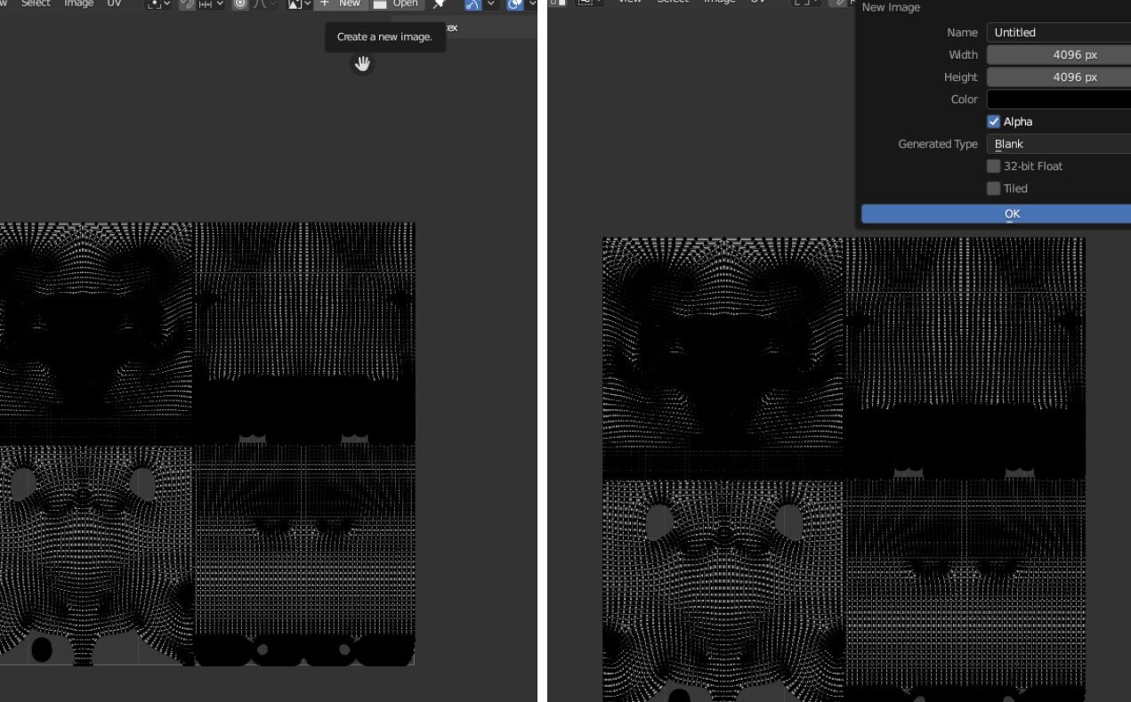
The “Image” Panel in the UV Editor has a field called “Source”. Let’s change this from “Generated” to “UDIM Tiles”:

The UV grid we’re currently using is now the first tile of our UDIM array. To add more tiles, let’s hit the “+” icon to the right of the list and add 3 more tiles.

Once that’s done, we can now take each of our islands and pack them into their own tile:
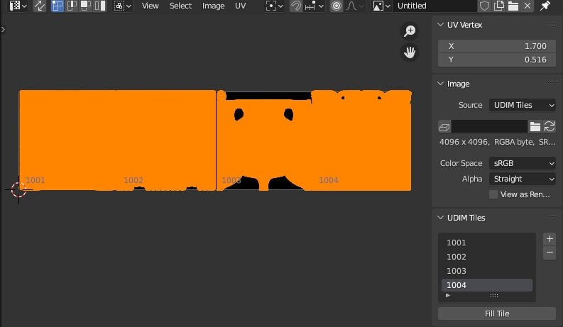
We now have our character ready for texturing! Let’s say we’ve run it through a multiresolution modifier, sculpted some additional detail and exported it out for Substance Painter (again, software like MARI or other alternatives will most likely have support for UDIMs).

In Painter, all we need to do is tick “Use UV Tile workflow”, and choose one of the 2 options available. In this case, we’ll choose the first.

Here is a glimpse of the character with some texture applied, and the Texture Set List panel, indicating that all UDIM tiles have been read and are active. As we can see on the tiles to the right, we can  paint in details for the head with the full resolution of a 4K map AND seamlessly continue painting the rest of the body at a proportionally high resolution!

In the scene we’ll be rendering however, the legs and feet won’t be visible, so for now, we could change the resolution of UDIM Tile 1004 to a smaller map size. The torso (1003) will hardly be seen so we could change its map size to 2048.

We see that the window on the right now indicates the map sizes of each UDIM Tile, and from the left we can see the updated model. This implies that with UDIMs, we also have the ability to quickly optimise our textures for whatever the situation calls for. Should this character decide to go streaking in the desert at some point, we can load our Painter file and adjust accordingly.

In Painter, the ID of the tile will be added as a suffix to each texture image that is exported.

Back in Blender, when importing our new textures into our character, we’ll need to select the maps that end with the suffix “1001” and  set the source of each imported image to “UDIM Tiles” to see our textures properly distributed across our UVs.

And that’s it! We’ve successfully created our first UDIM setup in Blender!

In summary, UDIMs, or "U-Dimension" texture mapping, can greatly benefit a 3D artist's workflow by allowing for the creation of high-resolution textures that can be applied to a model without sacrificing detail or resolution. UDIMs are typically used in situations where a model requires high-resolution textures, such as in film and game production, where high-quality and detailed textures are essential for achieving realistic and immersive environments.

By dividing a texture into multiple tiles, UDIMs enable artists to work on different sections of a texture simultaneously, allowing for more efficient texturing workflows. They also provide greater flexibility for texture scaling and enable artists to reuse and repurpose textures for multiple models and scenes.

Overall, UDIMs have become an essential tool for 3D artists, providing the ability to create highly detailed and realistic textures for complex models, while also streamlining the texturing process and improving efficiency. As always, we hope this was helpful! Have fun experimenting with UDIMs, and Happy Rendering!

----

Originally published at https://garagefarm.net.

Best practices for using online render farms with 3ds Max

Tutorial / 01 March 2023

By Tom Greenwood 

An online render farm is a network of computers built specifically for 3D rendering that can be accessed remotely over the internet. They’re a fantastic tool for 3D artists for two reasons - first because they allow us to render large and complex scenes in a shorter amount of time, and second because the work is done on remote machines our local workstations remain free to use for other things.

In this article, we’ll discuss how to best prepare your 3ds Max scenes for online rendering, how to submit them for rendering to the cloud, how to manage them and then how to assemble the files. There are many online render farms, but I’ll be using GarageFarm.NET as an example because that is the rendering service I’ve found best. I’m using 3ds Max and V-Ray, but the guidelines here should be helpful no matter what software you are using, and no matter which online render farm you choose. I’ve been using GarageFarm.NET for several years now because their prices are good, their render times are fast, and their customer service is fantastic and always available (very important!).

Preparing scenes locally

First - let’s talk about preparing our 3ds Max scenes for an online render farm. You’ll want to keep your file sizes down to have faster upload times, and you’ll want to have your objects organized well on layers. Neither of these is necessary - but they’ll keep your upload times down and if you encounter any issues you’ll be able to find them much faster. I’ve seen some less organized 3D artists referencing massive, 500+ mb TIFFs in their materials. This might not be a problem if you are rendering locally, but it’s going to cause problems when your entire file and all related assets are getting beamed up into space and back down to a render farm somewhere. So keep your assets to a reasonable size.

You also will want to avoid using xrefs and vray proxies. I use xrefs in some cases (usually for large amounts of vegetation and trees or for large amounts of surrounding buildings) but I never use V-Ray proxies as online render farms often don’t handle them well during the upload process and reassembly.

Lastly, I like to make sure that all my cameras are going to be rendering using the same Output size and orientation. One of the great benefits of using an online render farm such as GarageFarm.NET is that you can submit dozens of cameras simultaneously as long they all use the same orientation and resolution.

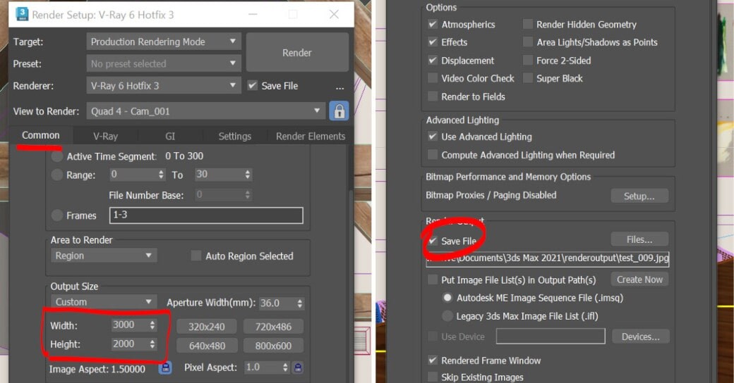
For your render settings, be sure to verify that your ‘Save File’ box is checked under the ‘Render Output’ section of the Common Parameters tab! Get your Render Elements set up and keep the ‘Elements Active’ box checked. You’ll also want to use bucket rendering - not progressive. Keep in mind that online render farms typically use the Common parameters setting for the output size, so make sure that your Output Size is set properly in the Common Parameters tab of your render settings, not the V-Ray tab, in which you should always check the box ‘Get resolution from MAX’ as well as the box for ‘Save RGB’ and ‘Separate render channels’ - that’s it!

Before you submit any project to an online rendering farm there are two crucial steps. The first is to save your work. The second is to run tests. For still images, I like to run a low-resolution progressive render locally in the V-Ray Frame Buffer to make sure my general lighting is good and catch any glaring issues. Then I do some fine-tuning tests, still locally in my Frame Buffer but this time bucket rendering and full resolution, but just rendering small regions to check various materials and see how they are coming out, particularly new materials.

Now that you’ve run your tests and feel that everything is looking good - make sure to switch the settings back to bucket rendering, and make sure that you do not have region render selected either in the Render Settings or in the Frame Buffer. Save your work and then submit it. With GarageFarm.NET, there will be a new menu in 3ds Max named ‘renderBeamer’ and you simply select ‘Beam it up’ to begin the process.

Rendering on GarageFarm.NET

GarageFarm.NET’s own simple software called renderBeamer checks the scene and then brings up a dialog box asking you to check which cameras to render and a few other settings you’ll not likely have to touch, and then it will upload your project. GarageFarm.NET renderBeamer allows you to monitor which projects you have uploaded, which need to be downloaded, but most of the active renderings. 

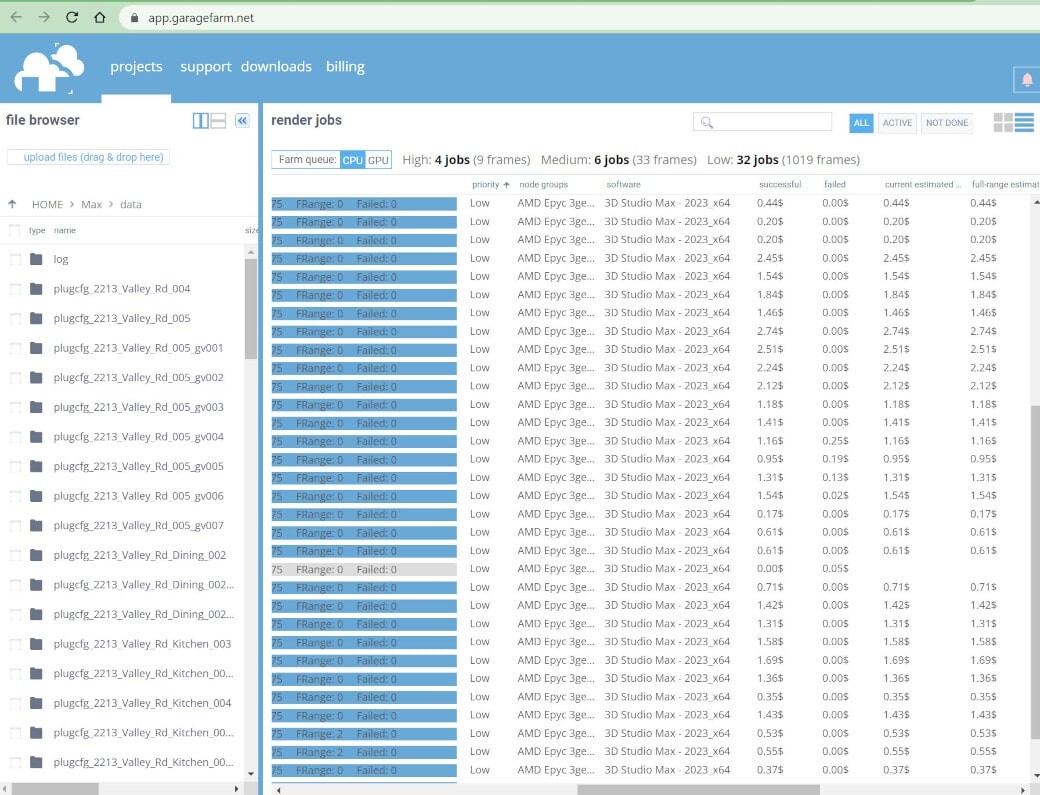
Once the job has been uploaded from Max and submitted using the renderBeamer app, you can monitor everything from a tab in the browser of your choice. You’ll be able to see which jobs are waiting to start, which jobs are active, and which jobs are done. Once a job has begun rendering, you’ll be able to get a live preview of how it’s going (if you are using GarageFarm.NET)

Rarely, a job will fail to render and you’ll see that in the tab. When this happens, you will follow the basic rules for troubleshooting your max file. I have never found a job to render perfectly on my local machine but fails when sent to the online render farm - which means it’s a problem with one of the files or assets, not with the online render farm. The only exception to this is when I was using V-Ray proxies. So the key is to run tests turning various layers on and off, at low resolution, to see which jobs fail and which succeed - this will help you narrow down the problematic asset or object.

The job, once complete, will download the rendering and the corresponding elements to a folder titled ‘Beamed’ on your local machine, where each camera will have its own folder designated by the max file name, the submission number, and the camera name. Every once and a while you should probably clear this folder out and archive old jobs (on GarageFarm.NET this can be done by selecting the old jobs and right-clicking, selecting ‘remove from list’).

I hope this has been helpful to you, and I promise that once you begin using online render farms you’ll never go back to rendering locally or building your own render farm. It is significantly faster and easier. Using an online rendering farm or cloud rendering service such as GarageFarm.NET is better in every single way, and the cost is minimal. Rendering locally bogs down your workstation and it’s very slow compared to a render farm. I used to have my own render farm in my office - it cost a fortune to build, it had to be maintained and the software on each of the computers had to be kept up to date with all software and plugins, and worst of all, get this: the electricity is used cost almost as much as it costs me to use GarageFarm.NET! My last tip is to practice using your online render farm a few times before you actually need it on a tight deadline. That way you’ll know that everything is working smoothly and you won’t have to worry about any unforeseen problems when it’s crunch time.

The statements and opinions expressed in this article may not accurately represent our render farm's features and support, as we update our software support on a regular basis. Please contact our team in our 24/7 live chat for inquiries.

----

Originally published at https://garagefarm.net.
Blender and render farms: common and avoidable pitfalls

Tutorial / 10 February 2023

Any Blender artist who creates or intends to create animated films that leverage all that the Cycles engine has to offer will have, at some point, after jumping all the various hurdles that come with producing animated characters against an elaborate backdrop replete with props, all painstakingly textured and enhanced with complex lighting and dynamic camera movement, sent their scenes to an online render farm and been unpleasantly surprised by the frames they got back.

We often associate sending projects off to render as the shiny ribbon at the end of a marathon of problem solving, optimising, questioning the purpose of our thankless existence, etcetera, but really it’s more like the penultimate waypoint of the journey, meant to tell us “you’re almost there, but don’t get cocky because I’ve got a few surprises left for you, pal!”

Over at our render farm, we’ve investigated and learned from quite a few problematic Blender renders, and are happy to report that the majority of the issues are a result of a little oversight, which is completely understandable at the last sprint of a project, with the deadline looming and the celebratory wrap up beers calling one’s name, which is why we’ve rounded up a list of things to check to avoid some of the common aforementioned nasty surprises that can be encountered after rendering a Blender project on a render farm service, for reference during the final leg of your 3D animation.

‍Are you tired of dealing with the headaches of rendering your Blender scenes on your own? Look no further than GarageFarm.NET. Our Blender render farm is dedicated to supporting Blender artists like you, with extensive compatibility for the Cycles engine and all its features. And if you do run into any issues, our live support team is available 24/7 to assist you.

Common pitfalls of rendering in Blender

The composite node conundrum 

If you assemble your render passes or add effects inside of Blender’s Compositor, it’s possible you may have been working on your node chain and at some point forgotten to plug the end of the final chain to the composite node.  

The composite node is what makes it to the final frame, and even if you are aware of this, it can be easy to overlook!

The render region (of regrets)

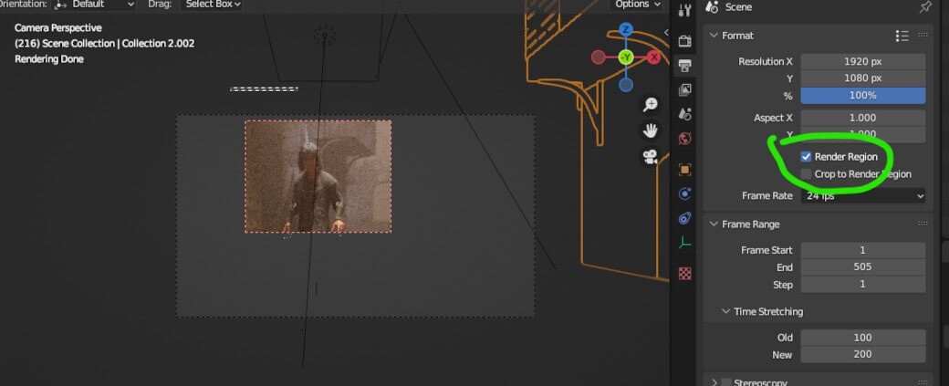
When working on a problematic area in a scene, it makes perfect sense to isolate that region in the viewport so we can make our changes and have the area of concern updated more quickly, but make sure to untick the render region box if you intend to have the whole frame rendered.

Simplify- the problem

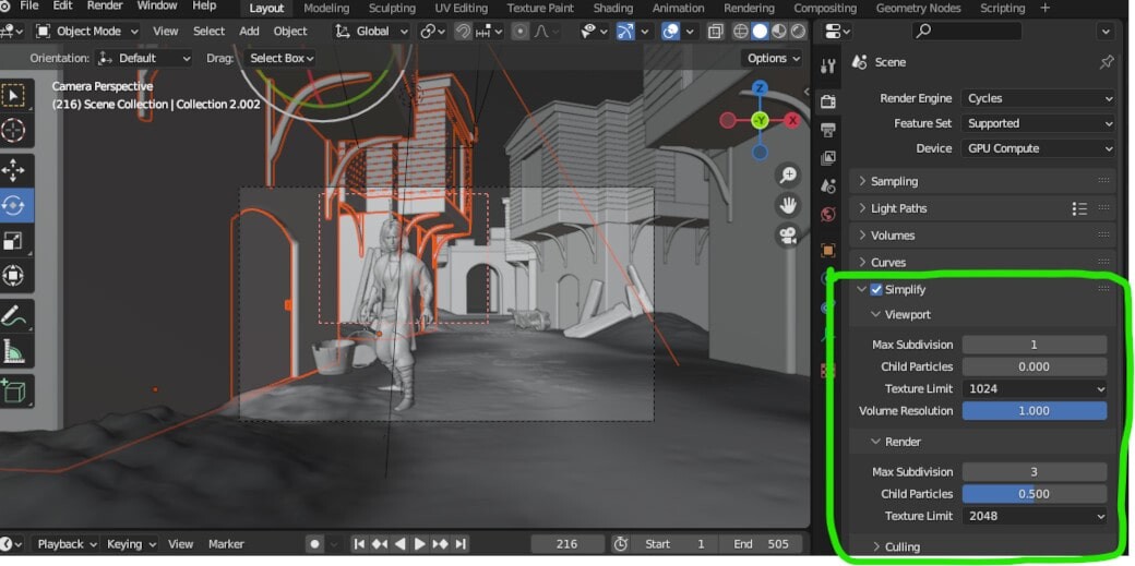
Likewise, in an attempt to expedite the refinement process in a project, the “simplify” option might have been enabled and left that way, which wouldn’t be much of a problem if the “render” values were untouched, but it may be the case that subdivision levels or child particles were reduced to crank out faster render tests, so it pays to make to untick “simplify” before sending off a project as a rule of thumb.

Conflict-resolution

As a render farm service, we encourage extensive testing, especially for animation. Rendering a few frames out of a sequence in a lower resolution is good practice, but it’s important to make sure the final resolution is set before sending out a project. 

If you use the percentage field to change your resolution, it’s possible that some render farms may display the values set in the x and y fields, but will render the values after the percentage override is applied, so triple check just in case!

It’s always Denoise ones

The Denoiser is a boon to every 3D artist, don’t get us wrong! We remember the days of clunky hacks to get away with fewer samples, and we don’t think of them fondly. But, when time is no longer an issue (as is the case when using a rendering farm) you may want to render your frames in their full sampled, unfiltered glory! 

Be sure to check the tickbox in the render settings, and in case you’ve enabled Denoising Data in the render passes tab, double check your compositor node chain! 

It should be pointed out that the modern online render farm will provide a plugin that will check your projects and warn you of some of these possible oversights as well as a few others (ours does!), but it’s never redundant to be absolutely sure that everything is in order before uploading a .blend, regardless of where you choose to render your projects. Just having to re-upload projects because of simple mistakes can take up more precious time than you’re comfortable with!In summary, here’s a quick checklist you can refer to before uploading to a render farm:

  • A. Check that the Compositor output node has your final node chain connected to it
  • B. Check that the Render Region is or isn’t enabled, depending on your intentions
  • C. Check that Simplify is or isn’t enabled, depending on your intentions
  • D. Check your resolution settings - especially the percentage slider! 
  • E. Check the Denoiser toggle in the render settings, and your node chain if you enabled the Denoise Filter render pass. We hope this was an entertaining and useful read, and that we see you on the farm someday. Stay vigilant, and as always, Happy Rendering!

---

Originally published at https://garagefarm.net.

How to move cameras in Blender like a cinematographer using Cinepack

Tutorial / 30 January 2023

It would be redundant at this point to reiterate how Blender is a powerful means to create complex 3D animations, and there’s no shortage of great material online that goes into the fundamentals of 3D production. Still, one of the commonly overlooked aspects of creating a visually compelling animation or film is camera movement. How a camera is positioned, moved, and framed can significantly impact how the audience perceives a scene. 

In the field of cinematography, camera movement is used to create visual interest, establish spatial relationships between objects, and evoke specific emotions in the viewer. Understanding how to move cameras in Blender to apply cinematography concepts is essential for creating engaging and impactful animated 3D storytelling. Thanks to Lewis Martin of the Blender Community, getting started is much easier!

(If you need a cloud rendering service for your animations with superb Blender support, check out our Blender render farm!)

Cinepack is a collection of pre-animated cameras designed specifically to help users make cinematic camera moves in Blender. It provides advanced camera rigs, constraints, and drivers that can be used to create precise and realistic shots. The Cinepack addon provides customizable camera moves, allowing you to use the provided camera moves as is, or edit them to suit your specific needs. These camera moves can also serve as a foundation for creating more complex camera movements. Additionally, the addon allows for instant previews of all camera moves.


Setting up Cinepack

  1. Purchase and download the Cinepack addon from Lewis’ shop on Blender Market. Make sure you have the correct version of the addon for your version of Blender.
  2. In Blender, go to the "Edit" menu and select "Preferences."
  3. In the "Preferences" window, go to the "Add-ons" tab.
  4. Click on the "Install" button, and navigate to the location where you downloaded the Cinepack Addon. Select the file and click on the "Open" button to install it.
  5. Once the addon is installed, you can activate it by going to the "Add-ons" tab in the "Preferences" window, and searching for "Cinepack." Check the box next to the addon's name to enable it.
  6. With the Cinepack Addon enabled, you can start using it in Blender. The Cinepack tools will be available in the 3D Viewport, in the Properties panel, and in the Tools menu.
  7. You can then access the Cinepack tools from the Properties panel.


How to move cameras in Blender with Cinepack

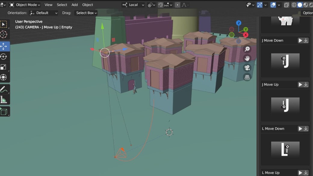
You can select any of the available categories on the top of the panel, and you can preview each of the moves below by pressing the play button icon to the right of the move’s name. 

The preview will play on your operating system’s media player. The screencap above is from the preview of the move labelled “J Move Down”.

Clicking on the download icon next to the play button icon will append the camera into your scene.

The Camera rigs will differ slightly depending on the nature of the movement, but each of them will have an empty in the shape of an arrow. Use this empty to adjust the camera rig’s position. 

Selecting the camera itself will allow you to adjust the settings of the constraints used in the rig, if any.

In the case of this particular shot, the camera has an Influence constraint that causes it to follow the shape of the curve as it is moved to accomplish the “J” movement. 

Adjusting the Influence slider value will offset the camera from the curve and affect how closely it adheres to the shape of the curve. 

Depending on the camera movement, you’ll find keyframes on the camera object, the empty objects that are part of the rig, or a parameter within the camera object or constraint. You can change the animation duration, start and end points by moving the keys in the timeline. You can also use the NLA editor to push keyframes down into an action that you can then reverse and combine with any hand animations you may want to add.

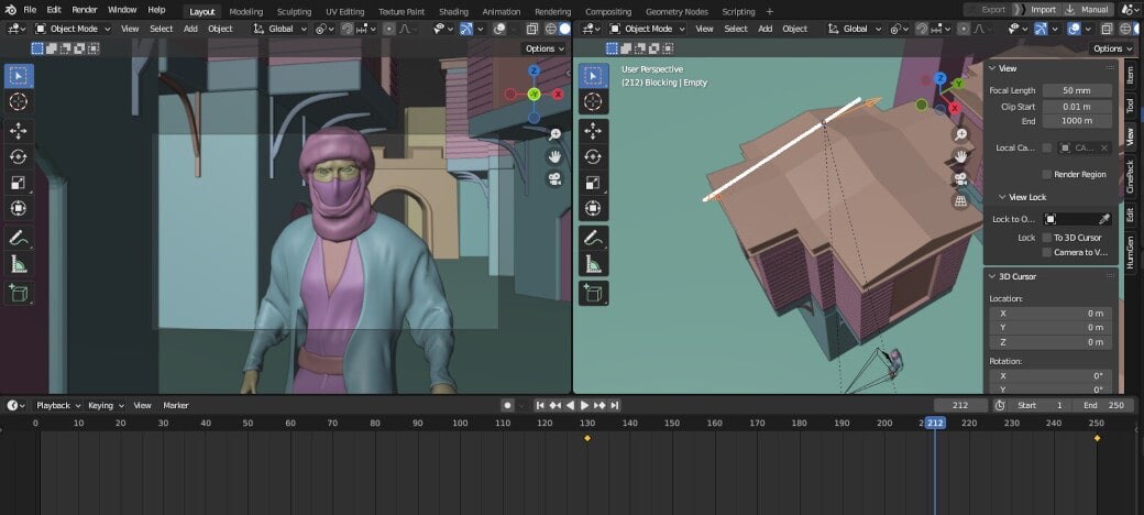
In the screencap above for example, notice that the camera points at the character at the starting frame. The screencap below shows the end camera position of the “J” movement: 

Left viewport: camera view towards the end of the animation. Right: Camera placement in the scene.

Let’s say we wanted to reverse the shot (There’s actually a rig for the reverse movement, but we’ll pretend there isn’t for the sake of demonstration). To do that, we could either switch the position of the start and end keyframes or, in the NLA editor, turn the keyframes into an action clip and enable “Reversed” on the action clip properties.

Now the camera ends on the character.

As you explore the different camera moves, it will benefit you to consider what animation, constraints, and parents are in play. Eventually, you will gain an understanding of how the camera rigs work, and you’ll be able to customize any camera move to match your idea for a shot. 

For instance, if we wanted to extend this shot so that the camera moves toward the character after the J move, we can animate the rig’s Empty after the camera settles on the character.

 Left: shot from camera POV Right: Camera Rig’s Empty with the path of motion after adding keyframes.

It’s typically best to animate using the control or Parent Empty for Camera rigs since many, like this particular rig, will have the camera constrained to a spline or another Empty in the object hierarchy.

Let’s say we wanted to add a little shake to the camera as it closes up on the character.
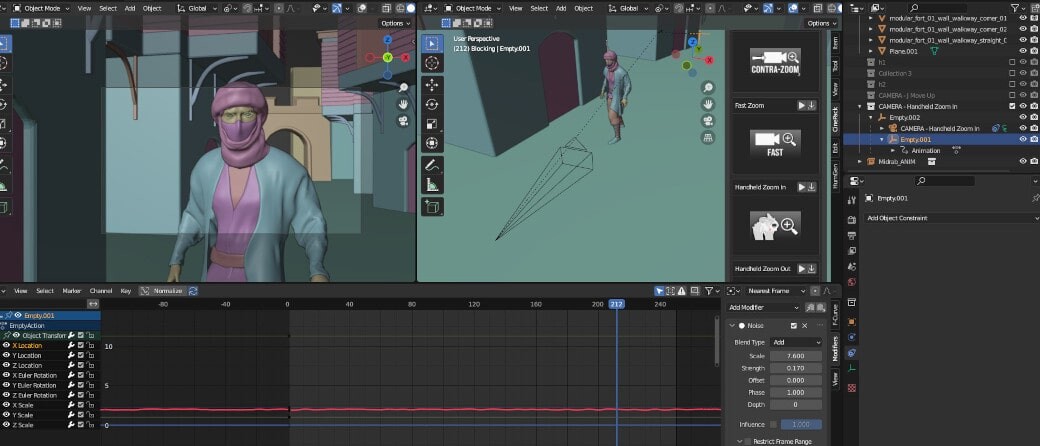
If we append “Handheld-Zoom in,” we’ll find that:

- The camera is constrained to an empty with an animation curve modifier called “Noise,” which accounts for the shake.
- The Zoom effect is achieved by animating the camera’s focal length instead of moving the rig.


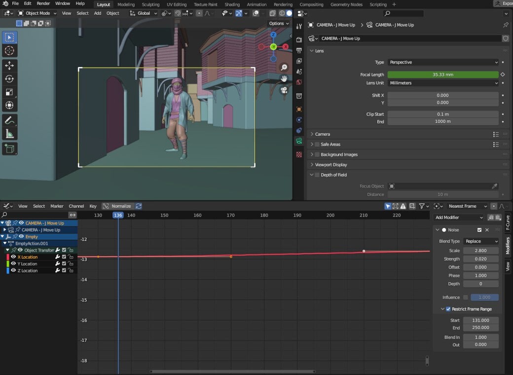
We can apply the same modifier to the appropriate channel on our animated Empty on the J Move rig, and also animate our focal length to add to the final effect. 


The Cinepack addon is a powerful tool that can assist you in achieving cinematic camera moves and is an excellent source of learning how to move cameras in Blender for your animated short films. To learn more about Cinematography itself, I recommend Studio Binder’s article on the subject. I hope this was helpful and as always, Happy Rendering! 

----

Originally published at https://garagefarm.net.

Gobos in lighting

Tutorial / 27 January 2023

Gobo lights, also known as "go-betweens," are essential elements in lighting design. These are typically small metal or glass patterns placed before a light source to create specific shapes or designs on a surface or stage. 

Gobo lights can be used in various settings and situations, including theater, film, television, and events, to add visual interest and depth to a scene. Gobos can also be a powerful technique for 3D rendering, especially because it would be impractical to create assets in a scene that will not be visible in the render. In this article we’ll learn about Gobo lights and how we can use them in our 3D projects.

A 3D render using Gobo lights

Before we get to it, consider using our render farm if you're working on a 3D project and want to apply Gobo lights to your animated sequences. With powerful hardware and fast turnaround times, we can help you bring your 3D projects to life quickly and cost-effectively. Don't let rendering bottlenecks hold you back – try our online render farm today and see the difference for yourself!

Uses of Gobo lights in lighting design

One common use of Gobo lights is to project patterns onto a stage or set to create a specific mood or atmosphere. For example, a Gobo light shaped like tree branches could create the illusion of a forest setting, while a Gobo light with a geometric pattern could give a futuristic feel. We can also use Gobo lights to simulate natural elements, such as sunlight filtering through leaves or the reflections of water on a surface.

A shot of a theatre production in which Gobo lights were used to create the illusion of a forest setting (source: http://stagelighting2314spring2017.blogspot.com/

In addition to creating atmosphere, Gobo lights can also add depth and dimension to a stage. By using Gobo lights with a gradient or fading effect, a lighting designer can create the illusion of distance or layers in a scene. This can be particularly effective in creating the illusion of a larger space or a more expansive environment.

Gobo lights are also quick and cheap solutions for practical effects, such as simulating the flickering of a candle or the passing of a car's headlights. These types of Gobo lights are often called "animation Gobo lights," as they create the illusion of movement from elements out of view.

Overall, Gobo lights are a versatile and valuable tool in lighting design. Whether used in physical lighting setups or simulated using texture maps or image planes in 3D rendering, Gobo lights can enhance the visual impact of a production in various ways. They can create atmosphere, add depth and dimension, and create practical effects, all of which can help make a scene more immersive and believable.

Gobo lights in 3D rendering

In the digital realm of 3D rendering, we can achieve Gobo light effects using texture maps or image planes. Texture maps are digital images applied to the surface of a 3D model to add detail and realism. As with any texture map, we can create Gobo maps by hand-painting, photo-editing, or procedurally generating patterns directly in our 3d software. 

When used as a gobo light, we can apply a texture to a light source and project it onto the 3D scene to create a similar effect as a physical gobo light. This allows us  3D artists to easily add complex patterns or textures to our scenes.

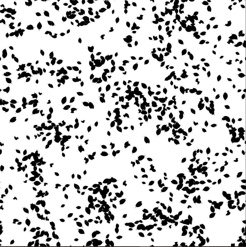
A texture map that will serve as a Gobo light

In this render, a Gobo light is shining down into a volumetric cube to imply moonlight shining through the leaves of  trees

Setting up a Gobo light in Blender 3D

Setting up a Gobo light in Blender is pretty straightforward, but there are a few steps you'll need to follow. First, you need to have at least one object and a spotlight in your scene.

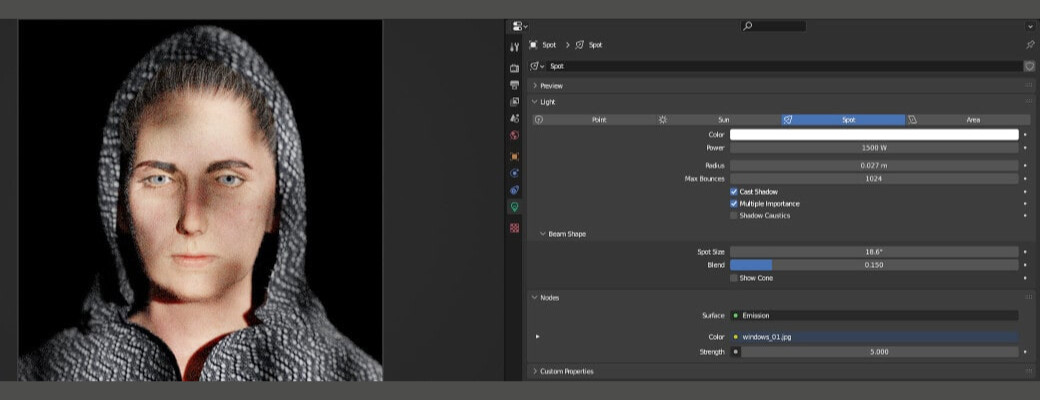
This is a portrait scene where the bust is lit by multiple lights. The spotlight is ideal for creating a Gobo effect.

To turn the spotlight into a Gobo light, you'll need to create a texture map to use as the Gobo. You can do this by either creating a new texture  map within Blender or importing an existing one. 

A texture map from the Gobos Light Textures addon by Bproduction-available on BlenderMarket

Enable “Use Nodes” on the spotlight and in the shader editor, add an image texture node and connect it to the input of the light’s Emission shader. 

For finer control, add a Vector>Mapping node and an Input>Texture Coordinate node as shown below: 

The Value node connected to the Scale input in the Mapping node just makes it easier to apply one value to  X, Y and Z.

Changing the scale values on the mapping node will control how the texture repeats.

Changing the values of the spotlight’s Radius parameter will affect the hardness of the Gobo shadows. 

Subtle uses of Gobo lights

Gobo lights can be used subtly to add a sense of realism and believability to a 3D render. Simulating light passing through obstacles, in general, can create a sense of depth and spatial awareness in the render, making it feel more like a real environment. 

Gobo lights can also be used to project subtle textures or patterns onto objects in the scene, such as the graining of wood or the texture of a stone wall. These subtle touches can help to add depth and detail to the render, making it feel more believable and realistic. Overall, Gobo lights can be a powerful tool for enhancing the believability of a 3D render, and when used effectively, they can help to create a more immersive and convincing environment.

A side-by-side comparison of a render without Gobos (left) and with Gobos (right)

While there are no distinct shadow patterns that suggest the influence of Gobos in the example above, the play of different textures from the light sources on the right side render lends more visual interest to the image (in the writer’s humble opinion).

In conclusion, Gobo lights are a powerful tool in lighting design that can add atmosphere, depth, and practical effects to a scene. Whether used in physical lighting setups or simulated in 3D rendering, Gobo lights can help bring a production to life more engagingly and realistically. 

By understanding the principles of Gobo light use and how they can be applied in different contexts, lighting designers and 3D artists can fully utilize the creative potential of Gobo lights to bring their visions to life. Whether you're just starting out in lighting design or are an experienced professional, Gobo lights are a valuable tool that can enhance your work in countless ways.

---

Originally published at https://garagefarm.net.

Texturing in Cinema 4D

Tutorial / 07 October 2022

When we talk about motion design and stunning realistic digital projects, one software immediately comes to mind: Cinema 4D. C4D is well known for its potential to create 3D projects pretty quickly and efficiently, allowing the designers to play with a wide range of modelling, deforming, simulating and material editing tools to achieve more and more interesting results on both still images and animations with a variety of rendering style options to make all sort of creatives happy. 

Before we continue, check out GarageFarm.NET’s Cinema 4D Renderfarm if you need quick and easy rendering power on your next project. New signups get $50 worth of starting credit, and a team of 3D experts will help you with any questions you might have at any time of the day and any day of the week. 

When it comes to creating outstanding renderings, what's essential, alongside high-quality modelling of the elements and characters, is setting the materials and the textures correctly to mimic as close as possible the materials of the natural world and their interaction with light.  

To achieve the photorealism we are aiming for, believe it or not, the secret is to introduce minor imperfections in the scene and the textures of the objects. In the real world, nothing is perfect and flawless, materials always present some sort of detail due to production processes or treatments and usage, they have minor dents here and there on the surface or have consumed paint along the corners, these details make the object interact with light in a very specific way so while texturing our scene we should take all these elements into account. 

A typical workflow while creating a 3D scene is to first create the general layout with a white or grey flat material, this way we can see all the elements and the composition for what they are without any distractions from materials, plus it saves time to work on the composition first. We will still be able to make adjustments afterwards. 

Once the 3D modelling is complete, and the scene is set, it's time to go through the C4D texturing process. Depending on the result we have in mind another good step to take would be to test the light settings and effects, editing the position and intensity of the light sources if necessary. This practice helps to have a quick preview of the general mood of the scene, and, as before, we can come back and adjust and edit at any time. 

Image by Marcin Kasperski https://masin.artstation.com/projects/mGPv9

 Now it's time to apply some materials and textures.

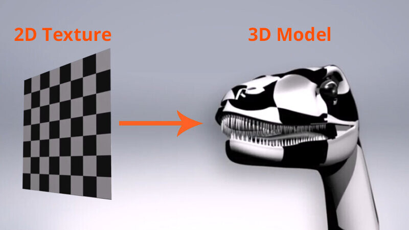
First of all, let's clarify what texturing means: texturing is the process of applying a 2D texture (that can be a photograph, a graphic pattern you created, an image of some specific details, etc.) to a 3D surface. In order to do so there are different techniques that we can use.

Probably the most popular one is UV mapping. UV mapping consists of a process of unwrapping the surface of our object. It helps to imagine our 3D object as origami, and the process of unwrapping is opening up the paper that creates our shape. Depending on the complexity of the shape, the map could be very complex. It might take a little while to figure out where to apply the seam lines, which is where inevitably, we have to “break” the shape to open and flatten the map. Seams are usually placed in hidden or less visible parts of the model. As we can imagine, this process requires some time and practice to achieve good results. 

2D texture applied to 3D model. Image from pluralsight.com

Highlighted in green are the seams of the UV map. Image from pluralsight.com

A second method to texture your 3D models is to use procedural materials. Many software programs, including Cinema 4D, 3ds Max, Maya and open-source software like Blender, offer this possibility.

C4D texturing can benefit from Cinema’s wide range of procedural materials, which means that the materials and textures are described using mathematical expressions and usually are visualized through nodes. The nodes are elements that perform a specific function in the equation that describes the material, from colour correction to camera distance, generating noises, gradients, patterns, flakes or scratches and more. They can be connected to each other, and their combination can create endless possibilities. Paired with an instant previewer, the user can always see how a specific node or group of nodes is affecting the material’s appearance. 

Some nodes can be connected directly to an image of our creation or found on the internet. Some operate only if the image is in greyscale to apply the specific function they perform, like surface bumps or displacement, just to mention a couple. To create the greyscale version of our textures, or prepare some other map that we might need to make our materials as realistic as possible, Adobe Photoshop comes to our aid.

Another helpful open-source tool that we can use to create our textures and maps is Materialize. This handy software is a sort of Photoshop for material creation, and starting from a full-colour image allows the user to define a series of secondary maps that can significantly improve the quality of the materials in our 3D projects; plus, it comes with an instant previewer that immediately shows the material properties, making the editing and adjusting process incredibly easy and user friendly.

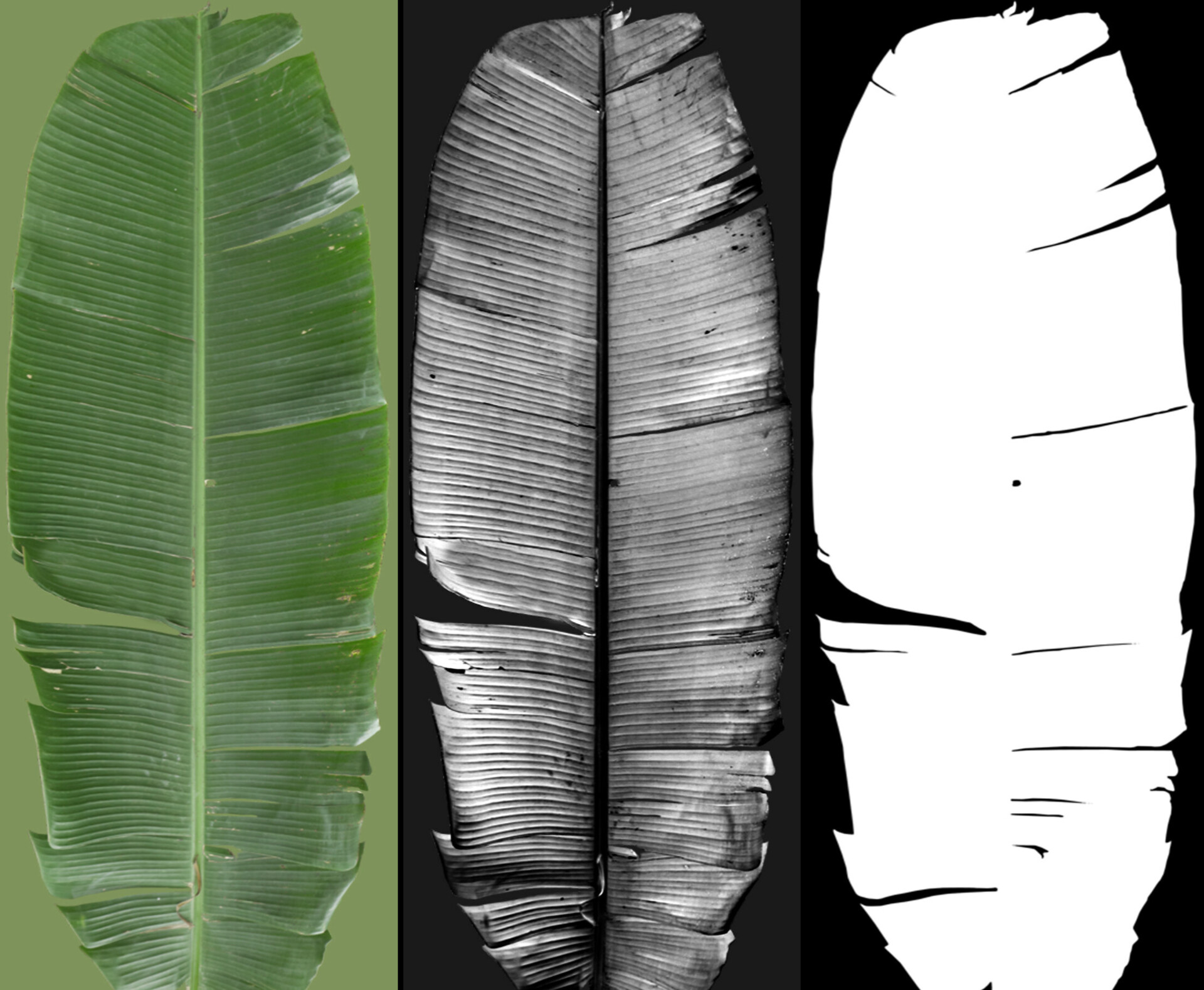
Example of a set of banana tree leaf textures. From left to right: colour texture, bump texture, mask texture

The above example shows the maps that I find more useful while texturing in Cinema 4D and that I think might produce good results. A good colour texture or image like the banana leaf above is a great starting point to get good final results in our renderings. In this case, to get the final result I aimed for, I used the bump map in greyscale to get the surface tridimensionality that every object in the real world possesses and final (but this could also be the first step) the mask that refines the geometry of the leaf and gives more realism to the model.

Example of the grey flat 3D model on the left and with only the colour texture applied on the right.

Notice how the colour texture is not enough to sufficiently describe the correct behaviour of the leaves in the banana plant model and how, despite the good quality of the image, the result is still flat and unappealing. Flagging the bump option in the material editor allows us to add the greyscale map we have and improve the quality of our material. 

Example of the banana tree with the bump map added.

As we can notice, the shape of our leaves is still too regular and not very realistic. Sometimes to save time and optimize our workflow it's better to design a more straightforward shape and adjust it with the help of a mask map. Mask maps are black-and-white images that define what is going to be visible (white) and what is going to be “cut off” (black). Often in 3D software like Cinema 4D and Blender, this map must be uploaded in the material editor settings alpha channel.

Transparency or opacity maps must be added to the Alpha channel section in the material editor when Texturing in Cinema 4D.

Banana tree with colour, bump and mask texture applied-Cinema 4D texturing preview.

Proceeding this way, we can achieve appealing results for all the composition’s materials and create stunning renderings. Keep in mind that every scene is unique, and according to the final result we want to achieve and the mood that we want to set, we should play with lights and colour settings accordingly. There is no preset formula to get a specific result, but this also means that the possibilities are endless, and the only limit is our creativity.


Happy rendering,
Sabrina Facchetti 

----

Originally published at https://garagefarm.net.
Using Cinema 4D’s Jiggle Deformer on an Alembic asset

Tutorial / 29 August 2022

Cinema 4D has always dominated the Mograph and Motion Design niche in the 3D industry, but if you’re coming from other software, you may be surprised to find that C4D also offers some interesting features that could really benefit character or creature animation workflows!

One such feature is the simple but powerful Jiggle Deformer. This deformer has been in Cinema 4D for a while and is great for giving 3D text (or any model, really) a sort of wobbly, gelatinous effect. Like any other deformer in C4D, it just needs to be set as a child of the mesh that’s to be affected to see any result. The deformer has several parameters that can be adjusted to fine-tune the “jiggle” as it were, but the deformer is only half of the fun.

Another great feature of Cinema is its seamless support of alembic, which makes it very easy to work with assets coming from other software including animated characters or creatures! In this article, we’ll export an animated pig model from Blender using the alembic format, and bring it into Cinema 4D S26 to add a jiggling effect. 


Before we get started if you’ve got scenes that need to be rendered quickly and without any hassle, consider our Cinema 4d render farm! We support all major DCCs and some relatively obscure ones, too! Our support team is available 24/7 and would be happy to answer any questions you might have.

And now, back to the program.


A few words about Alembic

Alembic is a 3D file exchange format developed by Sony and ILM, and its main purpose is to facilitate easier collaboration between studios that may be using different programs for 3D rendering. Alembic supports static and rigged meshes with animation, UVs,  lights, cameras, particles, curves, subdivision surface AND object hierarchies and the transform information in them. 

Alembic assets are sampled data from the original scene that was exported. This means they are less resource-intensive than their original forms, but also that any animation or particle simulation is baked into the asset, and cannot be modified as thoroughly as the original.


Exporting an animated asset as an Alembic File (in Blender)


This little pig will act as our test asset. We see that it’s been rigged and animated for a simple walk cycle. To export this as an Alembic file, we just need to select the model and the rig, and in the export group down, choose Alembic (.abc).

 In the succeeding menu, we can check our frame range, object scale and orientation. In this instance, we’ll leave everything as it is.


Importing Alembic into C4D

Importing the file into Cinema is a strange, but welcome process. We need only hit “open” in the File dropdown and select our .abc file.

We have our animated asset in Cinema, and everything works as it should. Notice, however, that the animation is baked into the mesh. We no longer have the rig to control, but that isn’t a problem for us in this case. 


The Jiggle Deformer

To add the Jiggle Deformer, we select our pig, hold down shift and choose Jiggle from the deformer drop-down.

 This should already place the deformer inside of the pig asset as a child on the outliner window.  Once we hit play we would already see it take effect. 

Of course, it would be better for the pig to not be entirely jiggly. It would make more sense for the jiggle to be isolated to the fatty areas of our porcine friend. To achieve this, we need to first convert our asset into an editable object. To do this, just select it and hit “c”.Now on the toolbar to the left of Cinema’s viewport, let’s choose the Paint Tool and begin painting the mesh.We get a sort of heat map on our pig that shows the unpainted areas as red, and the painted areas as yellow. We want to use varying amounts of weight on certain parts of the pig depending on what areas should jiggle more than others.

Here the most weight is allocated to the belly region and less is added to the neck and haunch areas, for example.

After painting, we can see that our asset has a new tag assigned to it on the outliner.

On the parameters of the Jiggle Deformer there are fields for maps that we can use to drive the effect. For the map field of the Stiffness parameter, we’ll hit the eyedropper tool and select the weight tag next to our object.

Then tick “invert”.

Now when we play back our animation we see that the effect is localized to where we added weight to the model. At this point, we can adjust the Strength, Stiffness and Structural sliders until we’re happy with the result.


We can now develop a shot for C4D rendering or export our changes out to a new alembic file that we can bring into other software.

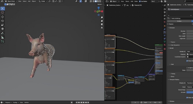
Here is the asset in Blender 3.2 once again. The textures were made for the original mesh but because the UV information is preserved in our alembic file, we can apply the textures without any problems. It was also very pleasantly surprising to see that adding hair particles to the alembic object was also possible!  Note that the textures and particles can be applied directly within Cinema as well. With a bit of lighting and camera work, we have a scene ready to render!

And that concludes this article! Cinema 4D seems to have quite a few features that would benefit less Motion Design-oriented workflows, and thanks to its strong integration of the Alembic format, we can leverage the best of Cinema and other DCCs that we have access to, and minimize the need to go through the (sometimes steep) learning curve of learning a new program.  We hope you found this useful, and as always, Happy Rendering.

---

Originally published at https://garagefarm.net.
Quick and dirty animated horses in Blender with Rigify Animbox

Tutorial / 28 July 2022


Ever need a shot of a character on horseback for your 3D animated short film? Maybe a mutant-feline charging at some hapless safari explorer? Well, it’s entirely possible now, even if you’ve never animated a quadruped in your life! 

Here’s an early iteration of the shot we’ll be looking at: 


‍I rendered the shot over at our Blender render farm. It was a real treat to be able to get my rendered frames in a matter of minutes! If you’re working on a short film or any animated sequence and could use some quick and easy render farm power, check us out!

If you found your way here and are not a Blender user, you may want to keep reading! Blender is becoming more and more powerful and has a cornucopia of free and equally powerful addons. You could generate your instant quadruped in Blender and send it to Maya, Cinema 4D or any other DCC with support for Alembic files, for example.

Enough of the preamble. Let’s get to it.

‍Rigify Animbox is a Blender animation add-on by Valangdance that offers a  range of incredibly useful features for rigging and animating, one of which is Rigify Zoo, which allows us to generate pre-animated quadrupeds that come with base meshes. We can use these base meshes to create our quadrupeds, or even as a simple reference for proportions to help us align our models to the rig. In this article, we’ll go over how I used Rigify Animbox to create the shot on the video tutorial.


Installing the add-on in Blender

Once you’ve downloaded the addon from Gumroad (and I do hope you left good ol’ Vangaldance a tip for his efforts!), simply open up your preferences in Blender, and in the add-ons tab, import and enable the .zip file.

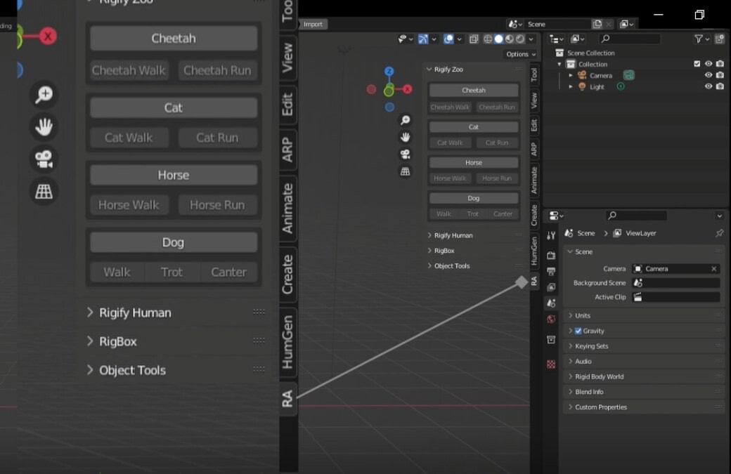
After, you’ll see a tab labeled “RA” on the right side of your viewport.

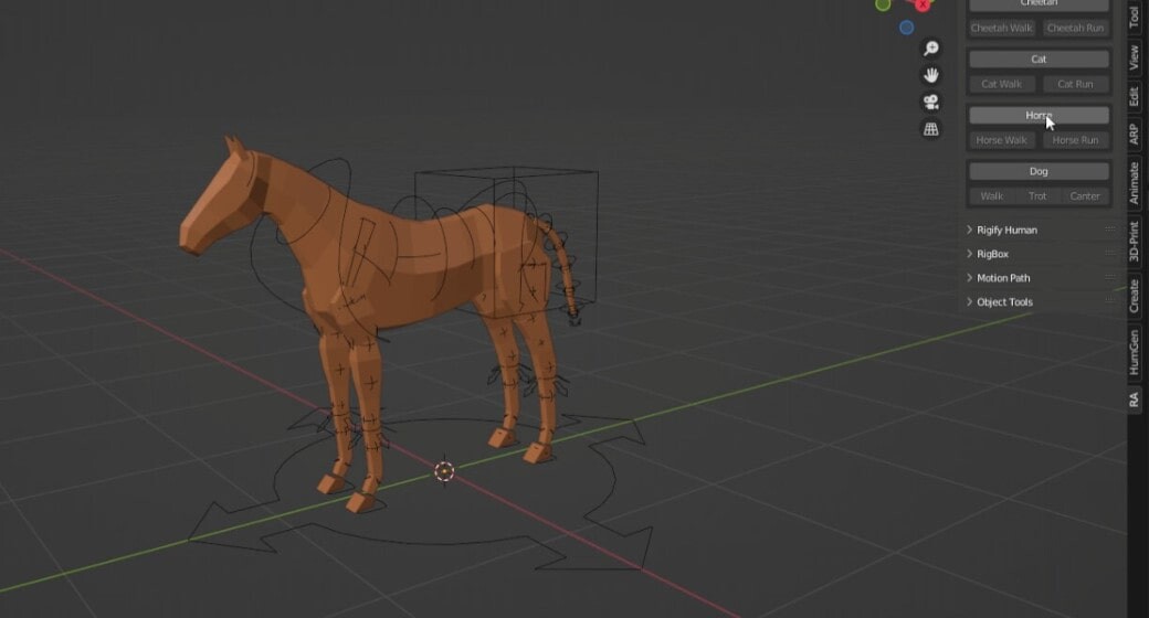
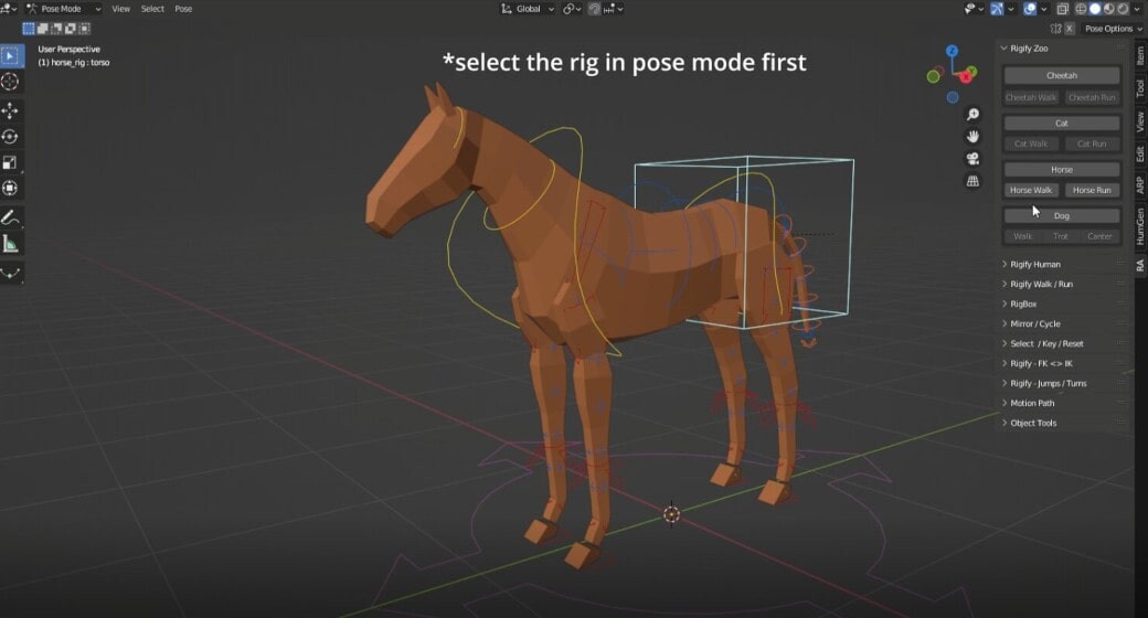
On the corresponding menu, you’ll see a list of quadruped presets you can load into your scene. For this project, I hit “Horse” and with the speed of a gunslinger's quick-draw I got this rigged base mesh:


Generating an animated quadruped

To get our quadrupeds moving, all we need to do is select the armature, enter Pose Mode and select a controller. On the right-side panel we can now choose to generate a walk or run cycle. I chose “Horse Walk” in this case.

We now have our very own moving four-legged friend.

The animation is a 32 frame cyclic walk, and if we were to extend our timeline to however many frames, we’ll see that the animation will just keep on looping, which in itself is a huge time saver!


Creating a forward direction

We can select the main root controller of our rig and begin to keyframe a forward movement. Blender will automatically set the resulting f-curve to a Bezier Interpolation. I personally found that setting the interpolation to Linear makes it easier to approximate a forward movement that was accurate to the walk animation.

Now when you try this out on your own scene, you might get lucky and have a nice forward movement for your quadruped. I didn’t. The initial keys I set covered a too long distance over a too long time period. That meant at several points in my horse’s walk, its feet would slide on the ground in a way that would make the late Michael Jackson roll over in his grave. 

Thankfully, the linear curve on my location channel made that clear right away. The quickest way to minimize this sliding is to simply select the endpoint of the curve and move it up until you get the right speed and distance for the pace of the walk cycle.

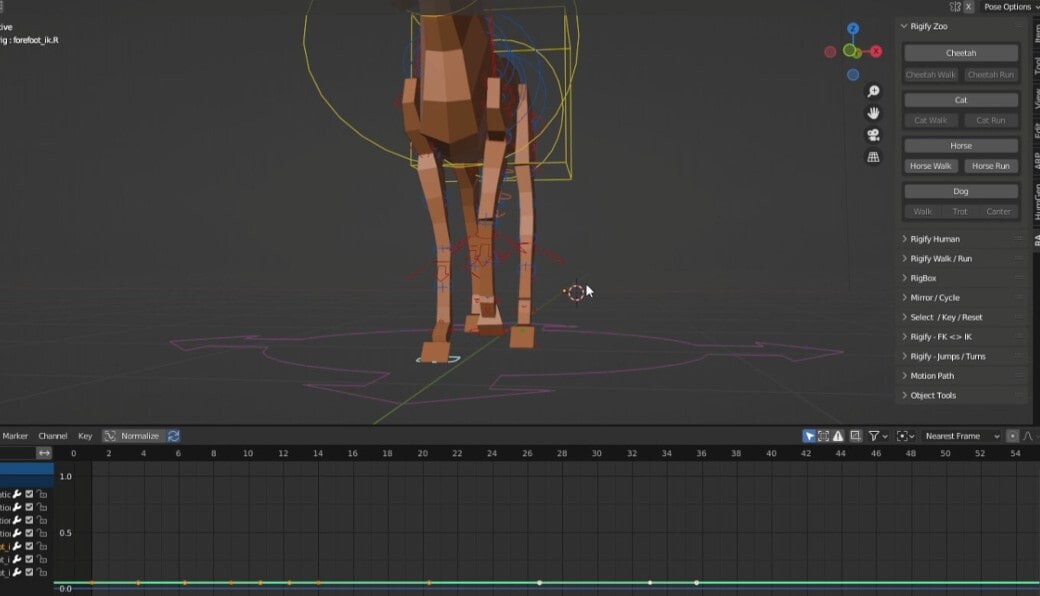
At this point, I had a satisfactory walk animation, but the horse’s front legs seemed a bit too far apart. To fix this I selected the front feet controllers and while still in the f-curve editor, I selected their x location channels and moved the curve up or down until I had both feet closer towards the center. 

Here the ik controller for the left foot is selected. The X location channel is isolated, and the channel’s curve is selected inside of the curve editor and moved up until the right foot is at the desired location in the 3D viewport.

Was it necessary? Probably not, but the animation looked better for it in my humble opinion. What really matters is that you can always make adjustments to your quadruped’s poses by moving the curves of certain controllers on whatever channel you need. You are not limited to what you get out of the (anim) box.


Turning the quadruped base mesh into an actual quadruped

We have our animation ready, and now comes the fun part. If you have a pre-modeled creature you could just use a lattice modifier and/or the Grab sculpting brush to align it with the rig, but it was more straightforward for me to just use the base mesh for this demo.

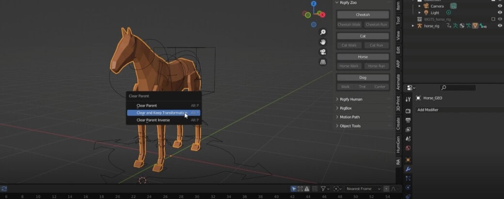
To start, I unparented the mesh from the armature and removed the armature modifier.

Select the rig and set it to “Rest Position” to have your base mesh at a neutral pose

With the mesh still selected, I entered Sculpt mode and with the Grab brush moved all the edges of the separated meshes towards their closest neighbors until there were no spaces between any of the geometry.

Make sure there are no spaces between any joints, or any disconnected meshes in the base object.

After, I used the remesh operation to actually merge all the geometry into one sculptable mesh. I chose a resolution that was enough for me to quickly lay in the major forms of the horse and increased the resolution as I moved into the latter stages of sculpting. If you’re interested in learning more about Sculpting, listen to what Louis du Mont has to say!

Once I finished, I remeshed it in Zbrush, created some UVs for it, and gave it a quick texture job. You could spend as long as you’d like (or can) on your own quadruped of course. More time will more often than not lead to much better results!

Alas, in my case this is all I could muster.

The good news is that working from the initial base mesh will give you something that you can just reparent to the rig! 

Automatic weights is the most straightforward way to get a rigged mesh without a need for much weight painting, if any at all.


Finishing up

I brought in a character I’ve been working on and put it inside its own collection in the scene. I then created an instance of that collection and parented it to one of the spine controllers on the horse rig.

To do this, I selected the instanced character first, then the horse’s armature and tabbed into Pose Mode. I then selected the controller that represented the part of the spine that undulated as the horse was moving and hit ctrl + P to parent the instance to Bone, enabling “keep transforms”.

This made it so that my character would move along with the horse and also reflect the vertical movements of the horse’s midsection as it moved through the poses of its walk cycle.

Later on, I decided to give the character a subtle animation as well. I retargeted a Mixamo sitting animation to the character’s rig and the collection instance parented to the horse updated immediately. To learn more about how to do this, have a look at this article.

I built a quick scene around my horse and rider and rendered it on GarageFarm. That’s how I ended up with a quick and dirty horse for my Blender animation!

---

This article was originally published on the GarageFarm.NET blog.

Blender update: Here’s what’s New In Blender 3.2

Tutorial / 27 July 2022

The folks at the Blender Foundation have yet again brought their dark horse DCC another step closer to being a force to be reckoned with in the 3D industry with their latest release with Blender 3.2. Many in the Blender community have already given us a rundown of the exciting additions and improvements, and we’re just as keen to share our list of what’s new and has us absolutely thrilled in version 3.2!

Before we go over our favourite features, we’re also happy to announce that we’ve already added support for Blender 3.2.0 over at our online render farm! New users get 50 USD worth of starting credits, and ALL Blender users rendering with us enjoy an automatic 33% discount. On top of that, they get generous volume discounts when they top-up credits!


And now, we’ll go over some of the goodies Blender 3.2 has to offer:

Light Groups 

Blender Light Groups make it possible to assign any number of lights in a scene to groups that become available as passes for compositing after a render. This cuts down the turnaround time spent in lighting scenes since even dramatic changes to light setups can be made in compositing. We were so eager to see this that we wrote about this feature while 3.2 was in its Beta stage, and made a more in-depth tutorial that comes with already rendered light passes that you can use to experiment with!

NLA Editor: tweak full stack 

This new feature is a little esoteric, which makes it completely understandable that it isn’t talked about a lot, but for anyone who uses the NLA editor for creating Mixamo animations with Blender, this is a godsend. 

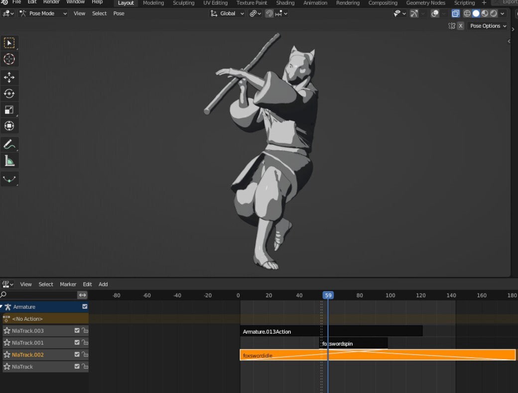
Above is an animated character with a stack of action strips in the NLA editor. The action strip highlighted in yellow and the action strip above it both contain individual keyframes that are combined together to create the character’s final movement. Previously, if we were to edit the keyframes on a strip below other strips, the strips above would be disabled. This made it difficult to make adjustments because there would be no visual feedback for the end result of all the combined action strips in the stack.

In this image, the previously highlighted strip is now in Blender’s OLD tweak mode. Notice the character’s pose is totally different. This is because we’re only seeing the keyframes inside of the highlighted strip, not the result when combined with the strip above.

In Blender 3.2 we get the option to “Start Tweaking Strip Action (Full Stack). Using this tweak setting, we now get to make adjustments and view the complete end result.

Notice how in this image, the same strip is in tweak mode, but we now we can adjust it while previewing changes in the final result (which is the combination of the current strip’s keyframes and those of the strip above it).

Polygon painting 

Concepting in Blender has been a real treat in the past few releases, and now it’s even better. A new painting toolset has been introduced to Sculpt Mode which makes it possible to paint with unprecedented thoroughness on unoptimized sculpts! 

The new Paint tool in sculpt mode comes with parameters to control tip hardness and size, wetness, Blending Modes and more to make painting over meshes as intuitive as digital painting on a 2D program.

The Mask by Color tool creates masks only within a selected color range (in this case the light greys of the eye areas). Adjusting the Threshold parameter can control the scope of the color range. The resulting mask can be further manipulated by the standard sculpt Mask operations.

The color Fill tool can be used to quickly Fill unmasked areas as well as change settings like Value, Contrast, Hue, Saturation and more with a couple of strokes.

The Smear tool works incredibly smoothly and can be used to blend colors into each other.

The Color Attributes are automatically connected to the Base Color input of shaders which means the painted data will immediately show in the render. 

And the pièce de résistance: when remeshing a sculpt, its color data can be preserved by enabling the corresponding switch in the remesher menu! 

Asset collections 

The Asset Browser is now five times more useful as it can finally support entire collections!This means that any assembly can now more easily be dragged and dropped into a scene. As soon as a collection is marked as an asset, a thumbnail is automatically generated including any textures on the objects within.

While this in itself is a major help, the implication of this is that if any change is made to the contents of the marked collection, all the instances created from the asset manager will automatically update.

In this screenshot, notice that as soon as the selected props were added to the Shelter Collection, all the instances of the collection in the scene now also come with those props!

Additionally, this makes it much easier to nest a variety of more complex assets together in a group. Think of a group of different trees that are keyframed to sway back and forth, or some farm animals moving around inside of a pen. 

The Curve Pen 

A humble but life-improving new tool, the Curve Pen makes working with complex curve patterns so much easier.

Whether creating some embossed ornamentation on pillars or just creating some really zany pretzels, the Curve Pen tool makes working with curves in general way less tedious, which is always welcome in Blender, particularly.

That completes our list of features, but this selection is by no means all that can be expected from 3.2. Motion Blur on Volumes, Shadow Caustics, the Video Sequencer improvements and the updates to Geometry Nodes and Grease Pencil are some of even more new features that have been generating excitement in the community as well! It goes without saying if you haven’t yet, download a copy of Blender 3.2 and get your hands dirty!

Blender is showing no signs of slowing down in its evolution, and as with every new release, we’re even more assured that it will be the prevalent tool of choice for the next generation of artists and designers.

---

This article was originally published on the GarageFarm.NET blog.

Quick animation look development with Blender’s Light Groups

Tutorial / 26 July 2022

Previously, we introduced the new Blender Light Groups feature in the upcoming 3.2 release. Aptly titled: How to use Blender Light Groups, we showed you how you could use the light passes inside of Blender’s compositor to make adjustments to our scene’s lighting on a rendered image, and how that saves a lot of time. (If you’re unfamiliar with Light Groups, give that article a read first!)

In this article, we’ll delve deeper into compositing with Light Group Passes on an animated shot I created on our render farm, and work on developing an atmospheric look in earnest!

If you’d like to follow along or just want to experiment on an already rendered sequence, you can find my rendered passes here.

Preparing passes for an animated sequence

Normally, we would render a couple of stills and work within Blender’s compositor to get the desired look on our shot, and so long as our node network is connected to the right output node, we could send our scene over to a render farm and have the look applied to all of the frames. 

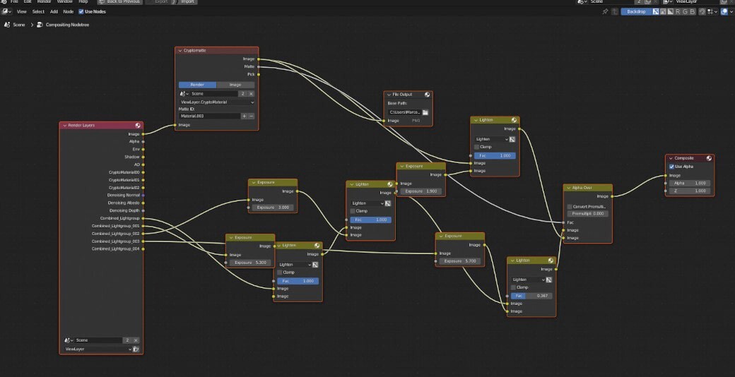
This node network assembles all light group passes in my scene and contains the adjustments I made. When I render out my animation, every frame will go through this node network before being saved as the final “composite” image.

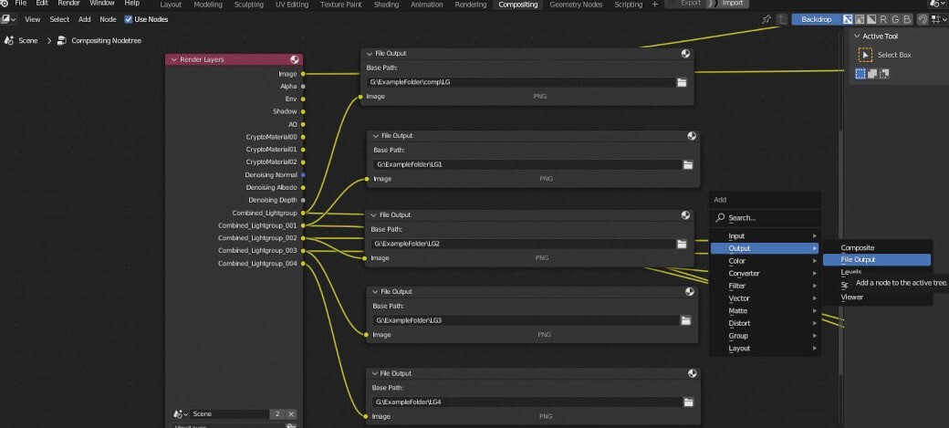
Problem is, If we had to make changes days later and we had closed Blender, we would have to go through the entire process again and that would be costly. We could, however, assign file output paths for each of our passes, so that they render along with our main frames.

Using the File Output Node in Blender’s Compositor, we can specify a path for each pass we want to be rendered out along with our main Composite Output.

A screenshot of my completed render in GarageFarm.NET along with the resulting files in my local directory. Note that originally, all frames will be stored in a single folder. I simply organized them into separate folders to more easily import them into Blender later on.

Having our passes on hand allows us to continue compositing without any fuss.  

‍In this image I have all of my light passes imported into the Blender compositor on a fresh scene. From here I can begin to combine passes as in the previous image to make my changes to the look of the shot. 

All light passes + a pass for the horse 


Compositing: Look 1

The final result

In this look, I was going for a warm, late afternoon vibe. Here’s how it’s done.


‍Combining Passes

I. To start, I used an Alpha Over node to place the horse pass over the environment pass (ENV). I did this so I could slightly brighten the horse at the beginning of the node network, but leaving the factor value low. This would allow the horse to be affected by the other light passes as I add them on, and I can raise the factor value later on as needed.

II. Next, using a color Mix node set to Add, I brought in the FILL pass and set the Fac value to 1. 

III. I repeated the step to bring in the KEY pass, but I brought the factor value down since in this look, I wanted the primary light to seem like it was behind the subjects and to the side.

IV. To sell this idea further, I added in the RIM pass and once more lowered the Fac value to match the intensity of the environment light. This light is already stylistic by nature and so it has to be subtle enough to be of service to the image without being distracting.

This network represents the basic “flow” of the final node chain. The succeeding adjustment nodes will be added between these nodes, but will not alter the sequence of how the passes are combined.


Adjustment 1: ENV COLOR AND LIGHT RAYS

I. I needed the environment pass to be a little stronger, so I brought in an Exposure node to crank it up.

II. After the Exposure node, I added a Color Balance node and brought the Lift Gamma and Gain colors towards the warmer end of the spectrum. I also brought the Lift Value down a smidge to give a little more contrast to the background of the scene.

III. I added a Sun Beams node and set the position to the upper left of the image, and adjusted the Ray Length value to taste. This node output has transparency so I used another Mix note set to Add to superimpose it on the output from the Color Balance node.

IV. As you can see, all these new nodes were set up before the Alpha Over node that combines the horse pass as mentioned in the earlier section.


Adjustment 2: FILL AND KEY PASSES

I. I brought in another Exposure node and a duplicate of the previous Color Balance node after the FILL pass to tweak its intensity and unify its color to that of the ENV pass. This network is combined with what I made in adjustment 1 via the Mix > Add node.

II. Once again I duplicated the Color Balance node to add to the Key Pass, this time giving the gain a yellowish tint. I should point out how being able to alter the Lift Gamma and Gain of each light pass gives us a level of control that I don’t believe was attainable in the previous versions of Blender. At the very end of this group of adjustments is the Mix>Add node that combines the KEY Pass to the chain.

Our resulting image so far

Adjustment 3: RIM

I. For the RIM Pass I added yet another Exposure node and after, another Color Balance node to tone down the intensity and unify the colors again.

II. This is the final combining node in the chain before leading to the Viewer and Composite output. Be sure to link the node before the Viewer Output node to the Composite Node as well, otherwise, when you hit render again, you will only see a black screen.

Here is the final image :

I ended up adjusting the colors even further to get a little more warmth in DaVinci Resolve as an afterthought, but this could easily be achieved using the Color Balance nodes inside of Blender. 

This concludes our discussion of the new Light Groups in Blender 3.2! Here is a comp of this and other looks I achieved after playing around with the passes even more.


I hope you found this useful and as always, Happy Rendering!

---

This article was published originally on the GarageFarm.NET blog.